
Componentes y Suministros
 |
|
× | 1 | |||
|
× | 1 | ||||
|
× | 1 | ||||
 |
|
× | 1 | |||
 |
|
× | 1 | |||
 |
|
× | 1 | |||
 |
|
× | 1 | |||
 |
|
× | 1 | |||
 |
|
× | 1 |
Aplicaciones y servicios en línea
 |
|
|||
|
Acerca de este proyecto
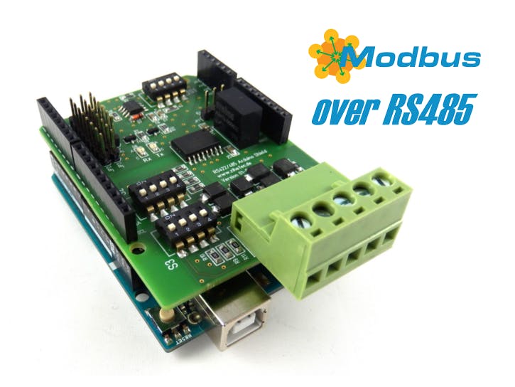
Modbus, un estándar de comunicación en serie, se ha convertido en un protocolo de comunicación estándar de facto y ahora es un medio comúnmente disponible para conectar dispositivos electrónicos industriales. En Modbus RTU y Modbus ASCII, RS485 se utiliza como capa física. Es posible usar un Arduino como esclavo (y con algunas restricciones también como maestro) en aplicaciones Modbus, pero se requiere una interfaz RS485. Nuestro Blindaje RS422 / RS485 es un escudo de comunicación serial completamente aislado galvánicamente diseñado para ser utilizado con Arduino UNO y otras placas compatibles como Arduino 101, STM Nucleo… Este escudo es la elección perfecta para este tipo de aplicaciones.
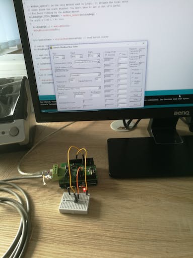
El objetivo de este documento es mostrar cómo crear con un Arduino UNO un dispositivo esclavo Modbus simple. Usaremos una PC como maestro Modbus.
herramientas y materiales
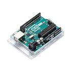
- Arduino UNO
- Escudo RS485 para Arduino
- No importa cual Adaptador RS485-USB para conexión a PC (o un menos caro)
Opcional:
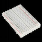
- tabla para cortar pan
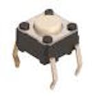
- Pulsador
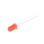
- LED rojo
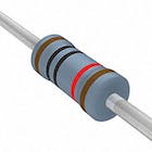
- resistencia de 220 ohmios
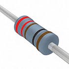
- Resistencia 10k
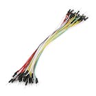
- Alambres de unión
software
- IDE de Arduino
- probador modbus
Cableado RS485:

El cableado es muy simple. Solo debe conectar los terminales A y B del blindaje con la línea A y B del sistema Modbus. Los terminales Y y Z no se utilizan para este tipo de aplicación. Para largas distancias, se recomienda utilizar pares trenzados para A y B.
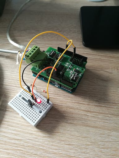
Cableado Arduino (opcional):
Se recomienda agregar un LED y un botón al Arduino para ver algunos efectos de la comunicación Modbus. Es opcional y no necesario.
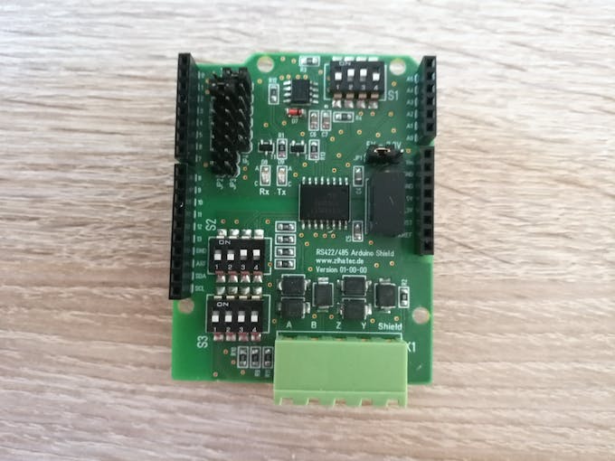
Configuración del interruptor DIP:
El escudo RS422/RS485 viene con 3 bancos de interruptores DIP. Debe configurar estos interruptores DIP para Modbus como se muestra en la imagen a continuación.
Interruptor 1:1-APAGADO 2-ENCENDIDO 3-ENCENDIDO 4-APAGADO
Interruptor 2: 1-APAGADO 2-APAGADO 3-ENCENDIDO 4-ENCENDIDO
Interruptor 3: 1-APAGADO o ENCENDIDO* 2-APAGADO 3-APAGADO 4-APAGADO
*Dependiendo de la posición del blindaje RS422/RS485 en la línea Modbus, debe activar o desactivar la resistencia de terminación. Gire la resistencia a la posición ON solo si el blindaje está en un extremo de la línea del bus. En todos los demás casos, deshabilite la resistencia de terminación:
Configuración de puentes:
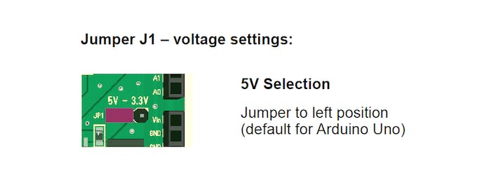
Puedes encontrar 3 áreas diferentes para ciclistas en el escudo. Muy importante es el puente JP1 para la tensión de alimentación. El Arduino UNO funciona con 5V internamente. Debe configurar este puente en la posición de 5 V (para placas de 3,3 V, por ejemplo, Arduino 101 en la posición de 3,3 V).
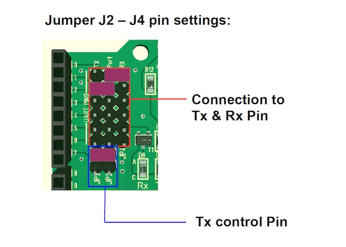
Además, coloque los puentes para los puertos de comunicación en la esquina superior izquierda como en la imagen de arriba. El UART interno en los puertos 0 y 1 se conectará en este caso a la interfaz RS485 del escudo.
Finalmente, debemos configurar el puente para el puerto de control RX/TX. No usamos este puente, porque está configurada la conmutación automática RX/TX.
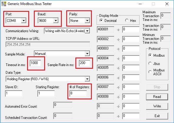
Instale el software del probador Modbus en la PC:
En este ejemplo, utilizaremos la PC como maestro Modbus. Necesitas descargar Modbustester. Descomprima el archivo zip en un nuevo directorio de su disco duro. Abra el software y edite los campos marcados como en la imagen de abajo. Debe conectar el adaptador USB-RS485 antes. Elija el puerto COM correcto para este adaptador en el probador modbus.
Programa Arduino:
Cargue el firmware en el IDE de Arduino para compilarlo y programarlo.
Pon a prueba tu trabajo:
¡Ahora es el momento de probar tu trabajo!
Puede presionar el botón Leer en Modbustester. Este comando leerá 8 bytes de la memoria de nuestro nuevo dispositivo esclavo. En la dirección 400008 puede encontrar el estado del botón. La dirección 400001 – 400006 contiene los valores de los puertos ADC.
Con el botón de escritura puede manipular los registros del esclavo. Puede ingresar en la dirección 400007 un 0 o un 1 para encender o apagar el LED.
codificado
diagramas

Por favor inicie sesión o regístrese para comentar.