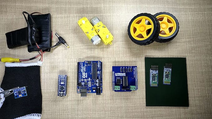
Componentes y suministros
 |
|
× | 1 | |||
 |
|
× | 1 | |||
 |
|
× | 2 | |||
 |
|
× | 1 | |||
 |
|
× | 2 | |||
|
× | 1 | ||||
 |
|
× | 1 | |||
 |
|
× | 2 |
Herramientas y máquinas necesarias.
 |
|
|||
 |
|
|||
 |
|
|||
 |
|
Aplicaciones y servicios en línea
 |
|
Acerca de este proyecto
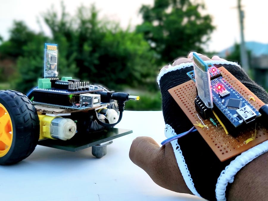
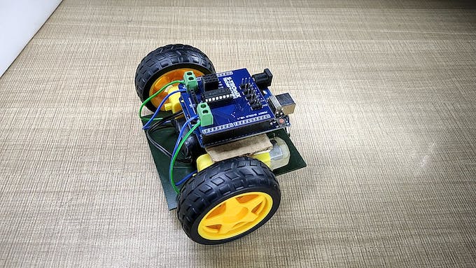
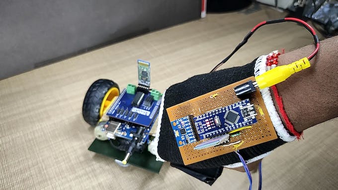
Se trata de cómo hacer un coche de control de gestos usted mismo. Básicamente, esta es una aplicación simple del giroscopio MPU-6050 de 3 ejes, acelerómetro. Puedes hacer muchas más cosas. al comprender cómo usarlo, cómo conectarlo con Arduino y cómo transferir sus datos a los módulos Bluetooth. En este artículo, me centraré en la comunicación Bluetooth a Bluetooth, entre dos módulos Bluetooth HC-05.
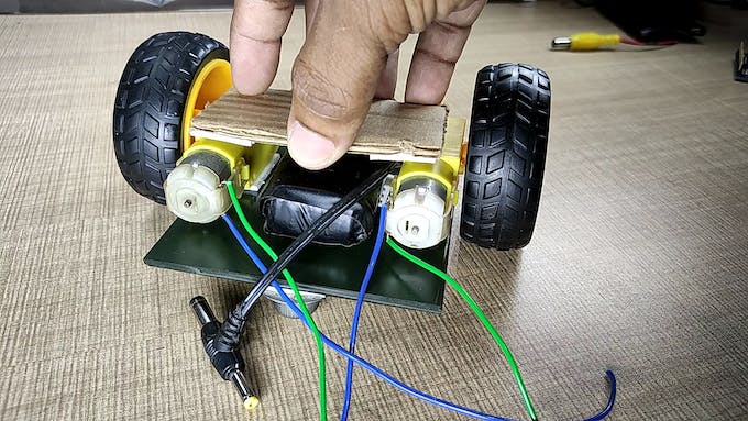
Siga el video para construir un cuerpo de robot y conexiones para este proyecto.
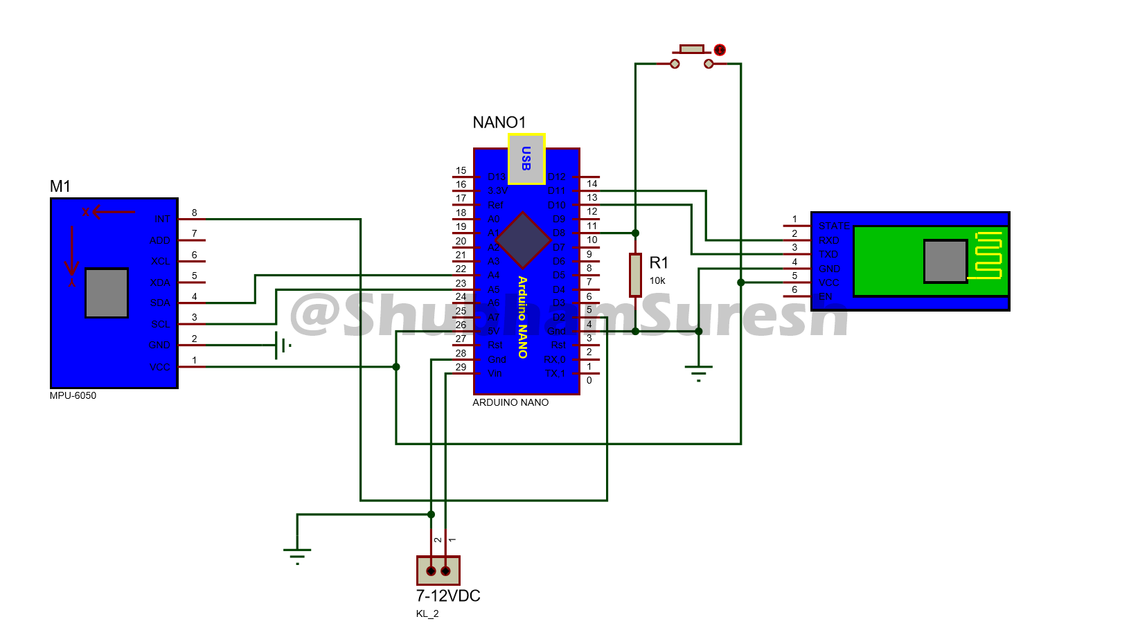
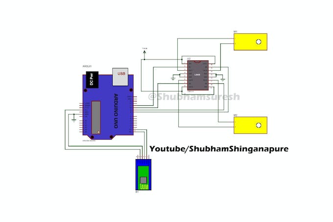
El diagrama de conexión para el robot y la unidad de transmisión se proporciona a continuación, puede consultarlo.
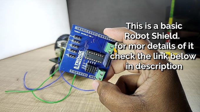
PCB de control directo utilizado en este proyecto de PCBway: https://www.pcbway.com/project/shareproject/How_to_Make_Arduino_Based_Edge_Avoiding_Robot.html

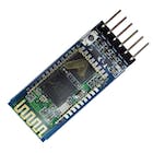
Ahora hablemos de la configuración del módulo Bluetooth. Básicamente, el módulo Bluetooth HC-05 viene con una configuración de fábrica de módulo esclavo. Esto significa que podemos enviar datos al módulo simplemente conectándolo. No se necesitan otras configuraciones para enviar datos desde dispositivos móviles al módulo HC-05. simplemente ingrese su contraseña predeterminada (1234/0000) para conectarlo. pero qué pasa si queremos enviar datos usando este módulo a otro mismo módulo o dispositivo móvil.
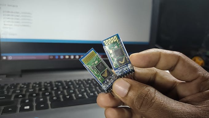

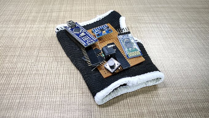
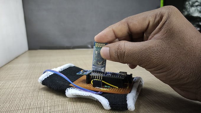
así que para hacer esto, primero debemos configurar estos dos módulos Bluetooth. para que puedan vincularse automáticamente entre sí después de encenderse. Aquí, el primer módulo actúa como un dispositivo esclavo, que recibirá señales de la unidad remota y se montará en el automóvil. Y configure el segundo como un dispositivo maestro que actuará como unidades transmisoras y enviará datos al dispositivo esclavo,
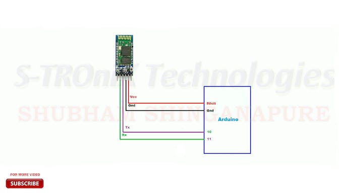
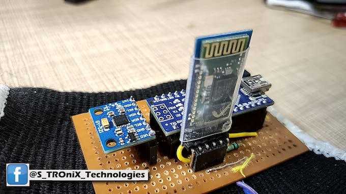
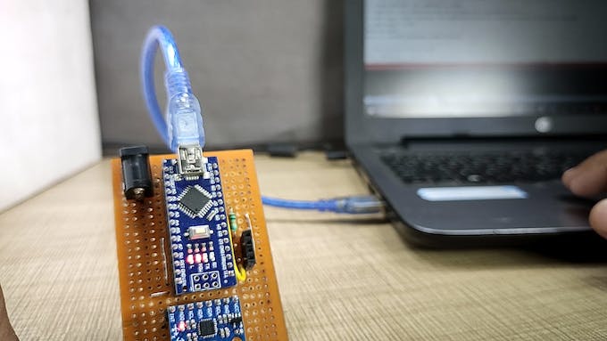
Así que primero configure el primer módulo Bluetooth como un dispositivo esclavo. para hacer esto, conéctelo a Arduino de acuerdo con este diagrama de cableado.
Y sube el código por nombre configure.
#include <SoftwareSerial.h>
SoftwareSerial BTSerial(10, 11); // RX | TX
void setup()
{
Serial.begin(9600);
Serial.println("Enter AT commands:");
BTSerial.begin(38400); // HC-05 default speed in AT command more
}
void loop()
{
// Keep reading from HC-05 and send to Arduino Serial Monitor
if (BTSerial.available())
Serial.write(BTSerial.read());
// Keep reading from Arduino Serial Monitor and send to HC-05
if (Serial.available())
BTSerial.write(Serial.read());
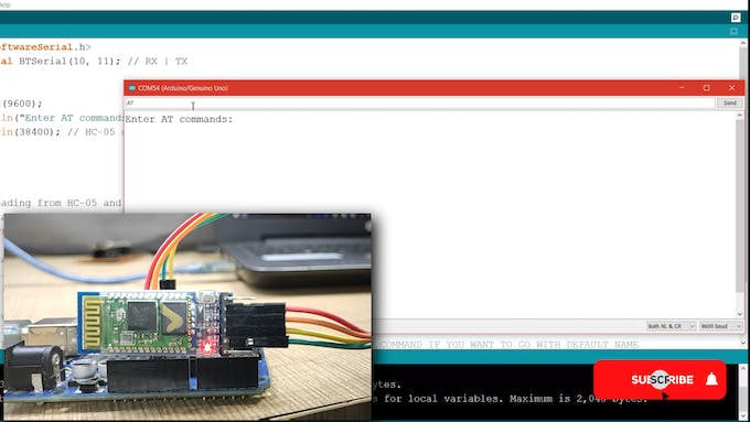
}Desconecte el módulo. Mantenga presionado el ky en el módulo y vuelva a conectarlo. Verás que el led del módulo parpadea más lentamente. Una vez cada 2 segundos. Significa que HC-05 está en modo comando AT. Ahora abra el monitor serial, cambie la tasa de baudios a 9600 y el tipo de salida como NL y CR. Ahora escriba AT en la bandeja de salida y envíelo. si responde ok, significa que todo está bien. Pero si no lo hace y responde con un error, envíe AT nuevamente. Hasta que responde con ok o comprueba las conexiones y envía AT de nuevo…
después de obtener la respuesta OK del módulo, ingrese los siguientes comandos uno por uno,
AT+ORGL y enviarlo. este comando establecerá el módulo a la configuración de fábrica.
AT+RMAAD este comando liberará el módulo de cualquier emparejamiento anterior
¿AT+UART? comprobar la tasa de baudios actual del módulo
AT+UART=38400, 0, 0 establece la tasa de baudios en 38400
EN+ROL? verifique el rol si es esclavo o maestro. responde con 0 o 1. si el módulo es esclavo responde 0 y si es maestro responderá con 1
establezca el rol como un dispositivo esclavo. ingrese AT+FUNCIÓN=0
¿AT+DIRECCIÓN? verifique la dirección del módulo.
Anota esta dirección. contestado por módulo. después de obtener esta dirección, se completa la configuración del módulo esclavo.
Ahora es el momento de configurar el segundo módulo Bluetooth como dispositivo maestro. Conecte este módulo a la placa Arduino e ingréselo en modo AT. como hicimos con el anterior.
Ingrese estos comandos AT en un orden dado.
EN+ORGL
AT+RMAAD
¿AT+UART?
AT+UART=38400, 0, 0
EN+ROL?
definir la función de este módulo como dispositivo maestro. PARA+FUNCIÓN=1
AT+CMODE=0 para que el módulo conecte solo un dispositivo. la configuración predeterminada es 0
ahora vincule este módulo con un dispositivo esclavo para hacer esto ingrese,
AT+BIND=»la dirección del módulo esclavo» y todo listo
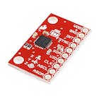
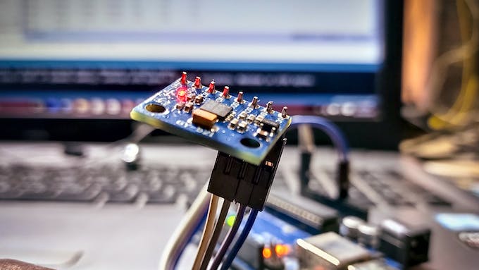
ahora instale las bibliotecas para el sensor MPU-6050 y la comunicación I2C. Dado que el sensor giroscópico MPU-6050 tiene una interfaz I2C. descargar bibliotecas y código fuente desde aquí: http://www.mediafire.com/file/l8mru5emulb8x93/gesture_control_robot.rar/file
si tiene estas bibliotecas preinstaladas, ignore esto.
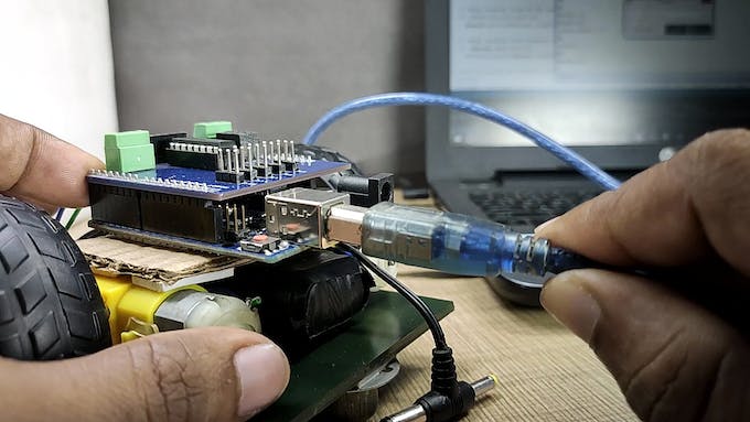
Ahora conecte la unidad de automóvil a la PC usando un cable USB. seleccione el puerto com y el tipo de tarjeta correctos. Y descargue el programa por su nombre «Gesture_controlled_Robot__car_unit_». Asegúrese de que la batería y el módulo Bluetooth no estén conectados al automóvil cuando descargue el programa.
//program by Shubham Shinganapure on 3-10-2019
//
//for Gesture controled Robotic Car
int lm1=8; //left motor output 1
int lm2=9; //left motor output 2
int rm1=10;  //right motor output 1
int rm2=11;  //right motor output 2
char d=0;
void setup()
{
pinMode(lm1,OUTPUT);
pinMode(lm2,OUTPUT);
pinMode(rm1,OUTPUT);
pinMode(rm2,OUTPUT);
Serial.begin(38400);
sTOP();
}
void loop()
{
if(Serial.available()>0)
{
d=Serial.read();
if(d=='F')
{
ForWard();
}
if(d=='B')
{
BackWard();
}
if(d=='L')
{
Left();
}
if(d=='R')
{
Right();
}
if(d=='S')
{
sTOP();
}
}
}
void ForWard()
{
digitalWrite(lm1,HIGH);
digitalWrite(lm2,LOW);
digitalWrite(rm1,HIGH);
digitalWrite(rm2,LOW);
}
void BackWard()
{
digitalWrite(lm1,LOW);
digitalWrite(lm2,HIGH);
digitalWrite(rm1,LOW);
digitalWrite(rm2,HIGH);
}
void Left()
{
digitalWrite(lm1,LOW);
digitalWrite(lm2,HIGH);
digitalWrite(rm1,HIGH);
digitalWrite(rm2,LOW);
}
void Right()
{
digitalWrite(lm1,HIGH);
digitalWrite(lm2,LOW);
digitalWrite(rm1,LOW);
digitalWrite(rm2,HIGH);
}
void sTOP()
{
digitalWrite(lm1,LOW);
digitalWrite(lm2,LOW);
digitalWrite(rm1,LOW);
digitalWrite(rm2,LOW);
}
Haz lo mismo con el control remoto. programa abierto por nombre de forma remota. y cárguelo en la unidad remota.
//program modified on 3/10/19 by // by Shubham Shinganapure.
//
//for Gesture controled Robotic Car (remote )
#include "I2Cdev.h"
#include "MPU6050_6Axis_MotionApps20.h"
//#include "MPU6050.h" // not necessary if using MotionApps include file
// Arduino Wire library is required if I2Cdev I2CDEV_ARDUINO_WIRE implementation
// is used in I2Cdev.h
#if I2CDEV_IMPLEMENTATION == I2CDEV_ARDUINO_WIRE
#include "Wire.h"
#endif
// class default I2C address is 0x68
// specific I2C addresses may be passed as a parameter here
// AD0 low = 0x68 (default for SparkFun breakout and InvenSense evaluation board)
// AD0 high = 0x69
MPU6050 mpu;
#define OUTPUT_READABLE_YAWPITCHROLL
// MPU control/status vars
bool dmpReady = false; // set true if DMP init was successful
uint8_t mpuIntStatus; // holds actual interrupt status byte from MPU
uint8_t devStatus; // return status after each device operation (0 = success, !0 = error)
uint16_t packetSize; // expected DMP packet size (default is 42 bytes)
uint16_t fifoCount; // count of all bytes currently in FIFO
uint8_t fifoBuffer[64]; // FIFO storage buffer
VectorFloat gravity;
Quaternion q;
float ypr[3]; // [yaw, pitch, roll] yaw/pitch/roll container and gravity vector
uint8_t teapotPacket[14] = { '$', 0x02, 0,0, 0,0, 0,0, 0,0, 0x00, 0x00, '\r', '\n' };
volatile bool mpuInterrupt = false; // indicates whether MPU interrupt pin has gone high
void dmpDataReady() {
mpuInterrupt = true;
}
#include <SoftwareSerial.h>
SoftwareSerial BTSerial(10, 11); // RX | TX
int bt=8;
int x =1;
void setup() {
#if I2CDEV_IMPLEMENTATION == I2CDEV_ARDUINO_WIRE
Wire.begin();
TWBR = 24; // 400kHz I2C clock (200kHz if CPU is 8MHz)
#elif I2CDEV_IMPLEMENTATION == I2CDEV_BUILTIN_FASTWIRE
Fastwire::setup(400, true);
#endif
// initialize serial communication
// (115200 chosen because it is required for Teapot Demo output, but it's
// really up to you depending on your project)
Serial.begin(115200);
BTSerial.begin(38400);
// while (!Serial); // wait for Leonardo enumeration, others continue immediately
Serial.println(F("Initializing I2C devices..."));
mpu.initialize();
// verify connection
Serial.println(F("Testing device connections..."));
Serial.println(mpu.testConnection() ? F("MPU6050 connection successful") : F("MPU6050 connection failed"));
// wait for ready
// load and configure the DMP
Serial.println(F("Initializing DMP..."));
devStatus = mpu.dmpInitialize();
// supply your own gyro offsets here, scaled for min sensitivity
mpu.setXGyroOffset(220);
mpu.setYGyroOffset(76);
mpu.setZGyroOffset(-85);
mpu.setZAccelOffset(1788);
// make sure it worked (returns 0 if so)
if (devStatus == 0) {
// turn on the DMP, now that it's ready
Serial.println(F("Enabling DMP..."));
mpu.setDMPEnabled(true);
// enable Arduino interrupt detection
Serial.println(F("Enabling interrupt detection (Arduino external interrupt 0)..."));
attachInterrupt(0, dmpDataReady, RISING);
mpuIntStatus = mpu.getIntStatus();
// set our DMP Ready flag so the main loop() function knows it's okay to use it
Serial.println(F("DMP ready! Waiting for first interrupt..."));
dmpReady = true;
// get expected DMP packet size for later comparison
packetSize = mpu.dmpGetFIFOPacketSize();
} else {
// ERROR!
// 1 = initial memory load failed
// 2 = DMP configuration updates failed
// (if it's going to break, usually the code will be 1)
Serial.print(F("DMP Initialization failed (code "));
Serial.print(devStatus);
Serial.println(F(")"));
}
// configure LED for output
pinMode(bt,INPUT);
}
// ================================================================
// === MAIN PROGRAM LOOP ===
// ================================================================
void loop() {
if(digitalRead(bt)==HIGH)
{
x++;
delay(150);
}
if((x%2)==0){
// if programming failed, don't try to do anything
if (!dmpReady) return;
// wait for MPU interrupt or extra packet(s) available
while (!mpuInterrupt && fifoCount < packetSize) {
// other program behavior stuff here
// .
// .
// .
// if you are really paranoid you can frequently test in between other
// stuff to see if mpuInterrupt is true, and if so, "break;" from the
// while() loop to immediately process the MPU data
// .
// .
// .
}
// reset interrupt flag and get INT_STATUS byte
mpuInterrupt = false;
mpuIntStatus = mpu.getIntStatus();
// get current FIFO count
fifoCount = mpu.getFIFOCount();
// check for overflow (this should never happen unless our code is too inefficient)
if ((mpuIntStatus & 0x10) || fifoCount == 1024) {
// reset so we can continue cleanly
mpu.resetFIFO();
Serial.println(F("FIFO overflow!"));
// otherwise, check for DMP data ready interrupt (this should happen frequently)
} else if (mpuIntStatus & 0x02) {
// wait for correct available data length, should be a VERY short wait
while (fifoCount < packetSize) fifoCount = mpu.getFIFOCount();
// read a packet from FIFO
mpu.getFIFOBytes(fifoBuffer, packetSize);
// track FIFO count here in case there is > 1 packet available
// (this lets us immediately read more without waiting for an interrupt)
fifoCount -= packetSize;
#ifdef OUTPUT_READABLE_YAWPITCHROLL
// display Euler angles in degrees
mpu.dmpGetQuaternion(&q, fifoBuffer);
mpu.dmpGetGravity(&gravity, &q);
mpu.dmpGetYawPitchRoll(ypr, &q, &gravity);
Serial.print("ypr\t");
Serial.print(ypr[0] * 180/M_PI);
Serial.print("\t");
Serial.print(ypr[1] * 180/M_PI);
Serial.print("\t");
Serial.println(ypr[2] * 180/M_PI);
if((ypr[1] * 180/M_PI)<= -25)
{BTSerial.write('F');
}
else if((ypr[1] * 180/M_PI)>= 25)
{BTSerial.write('B');
}
else if((ypr[2] * 180/M_PI)<= -25)
{BTSerial.write('L');
}
else if((ypr[2] * 180/M_PI)>= 20)
{BTSerial.write('R');
}
else{
BTSerial.write('S');
}
#endif
}
}
else{
BTSerial.write('S');
}
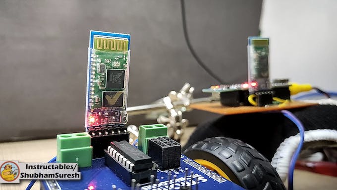
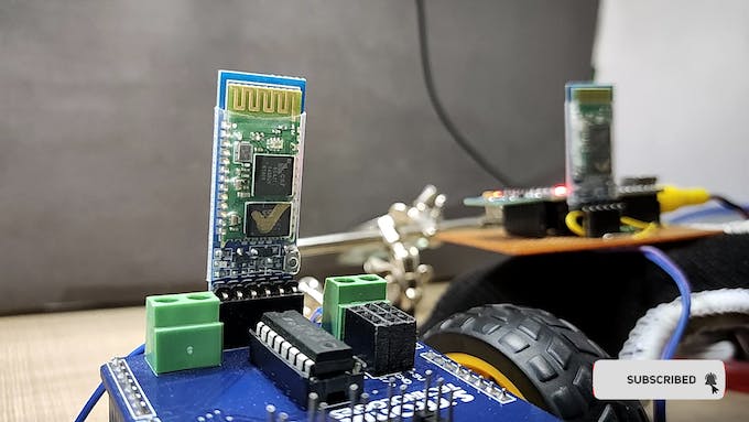
}Inserte el módulo Bluetooth esclavo en la unidad del automóvil y el módulo Bluetooth maestro en la unidad remota. Y todo está hecho.
Vamos a encenderlo y está listo para jugar…….
Espero que esto pueda ser de utilidad para usted. si es así, dale me gusta, comparte, comenta tu duda. Para otros proyectos de este tipo, sígueme! Apoya mi trabajo y suscríbete a mi canal en YouTube.
¡Gracias!
codificado
diagramas